Parameter input to the Initial IMP5 State actor
When running IMP5HCD in either IMP5HCD_sa or in the ETS, the machine paramters can be assigned using the actor Initial IMP5 State. To control this assignment, double click to configure the actor and fill in the pop-up panel. For more details follow the links to the NBI settings, the EC settings, the IC settings and the wall settings.
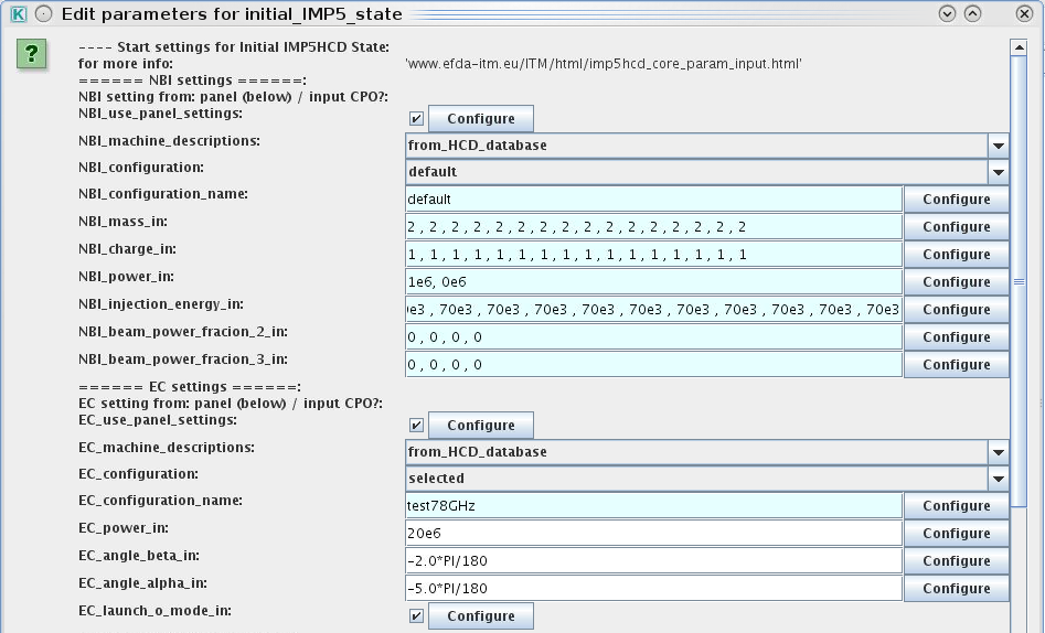
The NBI settings panel
The NBI settings panel is the list of variables following the line
===== NBI SETTINGS =====
Here is a description of the variables in this panel.
- NBI_use_panel_settings: If TRUE: use the NBI settings panel to configure the NBI system. If FALSE: ignore the NBI settings panel and use the input CPO.
- NBI_machine_descriptions: Select from where the NBI hardward description should be taken
- from_input_CPO: use the NBI hardware in the CPO provided by the UAL;
- from_HCD_database: uses the a HCD-database entry for the tokamak being simulated;
- from_codeparameters: specify the NBI settings in the codeparamters of the actor nbifiller.
- NBI_configuration: When using NBI data from NBI_machine_descriptions=from_HCD_database, then this parameter allow you to select different configurations: either you use the default or a selected configuration. In the latter case the name of the configuration is specified in NBI_configuration_name.
- NBI_configuration_name: When NBI_machine_descriptions=from_HCD_database and NBI_configuration=selected, then this parameter allow you to specify the name of your NBI configuration. The name is provided as a string and has to be one of the configurations in the list of NBI configurations. Note that the configuration is tied to the machine you are simulating, e.g. only ITER configurations can be used when simulating the ITER tokamak.
- NBI_mass_in: mass of injected species in atomic units. Vector over the beam injection units.
- NBI_charge_in: nuclear charge of injected species in atomic units. Vector over the beam injection units.
- NBI_power_in: power (W). Vector over the beam injection units.
- NBI_injection_energy_in: injection energy (J). Vector over the beam injection units.
- NBI_beam_power_fraction_2_in: fraction of the beam power injectedat half the nominal energy. Vector over the beam injection units.
- NBI_beam_power_fraction_3_in: fraction of the beam power injectedat a third of the nominal energy. Vector over the beam injection units.
Common NBI settings
| Machine | mass | charge | power | injection_energy | beam_power_fraction_2 | beam_power_fraction_3 |
|---|---|---|---|---|---|---|
| ITER | 2 | 1 | 33 MW | 1 MeV | 0 | 0 |
| JET (16 PINIs) | 2 | 1 | 25 MW (max 2.5 MW/PINI) | 80-140 keV | 0.15 | 0.08 |
| MAST | 2 | 1 | 4.0 MW | 60 keV | 0.15 | 0.08 |
| AUG (PINI 1-4) | 2 | 1 | 4 x 2.5 MW | 60 keV | 0.25 | 0.10 |
| AUG (PINI 5-8) | 2 | 1 | 4 x 2.5 MW | 93 keV | 0.25 | 0.10 |
| TCV* | 2 | 1 | 2.0 MW | 25 keV | 0.24 | 0.08 |
| DEMO | 2 | 1 | 90-200MW | 1-2 MeV | 0.0 | 0.0 |
NBI configurations available in the HCD-database
| Machine | Configuration name | Description |
|---|---|---|
| ITER | default | From the EDRG machine description database. Details: Unit 1 is On-axis and Unit 2 is Off-axis. Two gaussian components are assumed for the divergence : core (5mrad) and halo (15mrad). Unit R,Z,Phi calculated from avg of x,y,z coord. from datafiles of Otto. Tang_rad and angles from avg over beamlets angles. Beam divergences set to 5mrad assuming ideal core only component (halo 15mrad neglected). Past revisions of RUN2 contained 16 nbi units since we literally took the 4x4 layout of the cross section as with individual units. But there is a single power line and as such it is a single unit. Next datastructures should allow us to have type array to store arbitrary lenght r,z,phi,tang_rad,angle to describe any sort of layout in a coarse fashion. (2013) |
| JET | default | From the EDRG machine description database. Details: This file is valid for so-called UP1467 configuration (PINIs 1-4-6-7 of both Octants are upshifted with respect to their standard position). Excluding some few restart (duct conditioning) shots at the beginning of experiment campaigns (which should not be analysed anyway), this configuration is valid for the shotrange 52888-61931. The order of entries below is as follows: First Octant 4 PINI-1, PINI-2, ... PINI-8, then Octant 8 PINI-1, PINI-2, ..., PINI-8. For pow_frc_blt (fraction of power of a unit injected by a beamlet) it is assumed for the moment that all beamlets inject the same amount of power. (2013) |
| AUG | default | From the EDRG machine description database (2013). Details: This file does not contain details on the beamlets on each unit. We will have to get those later on. |
The EC settings panel
The EC settings panel is the list of variables following the line
===== EC SETTINGS =====
Here is a description of the variables in this panel.
- EC_use_panel_settings: If TRUE: use the EC settings panel to configure the EC system. If FALSE: ignore the EC settings panel and use the input CPO.
- EC_machine_descriptions: Select from where the EC hardware description should be taken:
- from_input_CPO: use the EC-configuration in the CPO provided by UAL-init;
- from_HCD_database: use the a HCD-database entry for the tokamak being simulated;
- from_codeparameters: specify the EC settings in the codeparamters of the actor addECant). For all three options, dynamic quantities like power, alpha, beta etc. are always set according to the NBI panel settings.
- from_input_CPO: use the EC-configuration in the CPO provided by UAL-init;
- EC_configuration: When using EC data from EC_machine_descriptions=from_HCD_database, then this parameter allow you to select different configurations: either you use the default or a selected configuration. In the latter case the name of the configuration is specified in EC_configuration_name.
- EC_configuration_name: When EC_machine_descriptions=from_HCD_database and EC_configuration=selected, then this parameter allow you to specify the name of your EC configuration. The name is provided as a string and has to be one of the configurations in the IMP5 EC-Antennas Database. Note that the configuration is tied to the machine you are simulating, e.g. only ITER configurations can be used when simulating the ITER tokamak.
- EC_power_in: power (W)
- EC_angle_alpha_in: Poloidal launching angle between the horizontal plane and the poloidal component of the nominal beam centerline (rad). Relation for to the component of the wave vector k: tan(alpha)=-k_z/k_R
- EC_angle_beta_in: Toroidal launching angle between the poloidal plane and the nominal beam centerline (rad). Relation for to the component of the wave vector k: sin(beta)=k_phi/|k|
Common EC settings
| Machine | EC_power_in | EC_angle_alpha_in (stearable range) | EC_angle_beta_in (stearable range) |
|---|---|---|---|
| AUG (*/EC_1, */EC_2, */EC_3, */EC_4) | 0.4 MW | (-4.3633231E-01 , 4.3633231E-01) rad | (-4.3633231E-01 , 4.3633231E-01) rad |
| AUG (*/EC_5, */EC_6, */EC_7, */EC_8) | 0.7 MW | (-4.3633231E-01 , 4.3633231E-01) rad | (-4.3633231E-01 , 4.3633231E-01) rad |
| DEMO1 | 40 MW | - rad | - rad |
| ITER (2009/UL_LSM) | 16 MW | (5.2359878E-01 , 9.5993109E-01) rad | (3.1415927E-01 , 3.1415927E-01) rad |
| ITER (2009/UL_USM) | 16 MW | (6.1086524E-01 , 1.0471976E+00) rad | (3.4906585E-01 , 3.4906585E-01) rad |
| ITER (2011/EL_BOT) | 8 MW | (-8.7266463E-02 , -8.7266463E-02) rad | (3.4906585E-01 , 6.9813170E-01) rad |
| ITER (2011/EL_MID) | 8 MW | (0.0000000E+00 , 0.0000000E+00) rad | (-6.9813170E-01 , -3.4906585E-01) rad |
| ITER (2011/EL_TOP) | 8 MW | (8.7266463E-02 , 8.7266463E-02) rad | (3.4906585E-01 , 6.9813170E-01) rad |
| ITER (2012/UL_LSM) | 16 MW | (5.2359878E-01 , 9.5993109E-01) rad | (3.4906585E-01 , 3.4906585E-01) rad |
| ITER (2012/UL_USM) | 16 MW | (6.1086524E-01 , 1.0471976E+00) rad | (3.4906585E-01 , 3.4906585E-01) rad |
| ITER (2013/EL_BOT) | 8 MW | (-1.7453293E-01 , 4.3633231E-01 rad | (4.3633231E-01 , 4.3633231E-01 rad |
| ITER (2013/EL_MID) | 8 MW | (0.0000000E+00 , 6.1086524E-01) rad | (4.3633231E-01 , 4.3633231E-01) rad |
| ITER (2013/EL_TOP) | 16 Mw | (-3.4906585E-01 , 2.6179939E-01) rad | (-3.4906585E-01 , -3.4906585E-01) rad |
| JET | 10 Mw | - rad | - rad |
EC configuration available in the HCD-database
| Machine | Configuration name | Description |
|---|---|---|
| AUG | LLLL |
Official AUG antenna configuration #1 .Provided by Joerg Stober and Walter Kasparek.
Gyrotrons configuration: f(EC_5)=105 GHz, f(EC_6)=105 GHz, f(EC_7)=105 GHz, f(EC_8)=105 GHz. NOTE: Anyone who wants to use the ITM database to plan EC experiments on AUG should get in contact with Joerg Stober, to check that the assumptions they have done are consistent. |
| AUG | LLLH |
Official AUG antenna configuration #2. Provided by Joerg Stober and Walter Kasparek.
Gyrotrons configuration: f(EC_5)=105 GHz, f(EC_6)=105 GHz, f(EC_7)=105 GHz, f(EC_8)=140 GHz. NOTE: Anyone who wants to use the ITM database to plan EC experiments on AUG should get in contact with Joerg Stober, to check that the assumptions they have done are consistent. |
| AUG | LLHL |
Official AUG antenna configuration #3. Provided by Joerg Stober and Walter Kasparek.
Gyrotrons configuration: f(EC_5)=105 GHz, f(EC_6)=105 GHz, f(EC_7)=140 GHz, f(EC_8)=105 GHz. NOTE: Anyone who wants to use the ITM database to plan EC experiments on AUG should get in contact with Joerg Stober, to check that the assumptions they have done are consistent. |
| AUG | LLHH |
Official AUG antenna configuration #4. Provided by Joerg Stober and Walter Kasparek.
Gyrotrons configuration: f(EC_5)=105 GHz, f(EC_6)=105 GHz, f(EC_7)=140 GHz, f(EC_8)=140 GHz. NOTE: Anyone who wants to use the ITM database to plan EC experiments on AUG should get in contact with Joerg Stober, to check that the assumptions they have done are consistent. |
| AUG | LHLL |
Official AUG antenna configuration #5. Provided by Joerg Stober and Walter Kasparek.
Gyrotrons configuration: f(EC_5)=105 GHz, f(EC_6)=140 GHz, f(EC_7)=105 GHz, f(EC_8)=105 GHz. NOTE: Anyone who wants to use the ITM database to plan EC experiments on AUG should get in contact with Joerg Stober, to check that the assumptions they have done are consistent. |
| AUG | LHLH |
Official AUG antenna configuration #6. Provided by Joerg Stober and Walter Kasparek.
Gyrotrons configuration: f(EC_5)=105 GHz, f(EC_6)=140 GHz, f(EC_7)=105 GHz, f(EC_8)=140 GHz. NOTE: Anyone who wants to use the ITM database to plan EC experiments on AUG should get in contact with Joerg Stober, to check that the assumptions they have done are consistent. |
| AUG | LHHL |
Official AUG antenna configuration #7. Provided by Joerg Stober and Walter Kasparek.
Gyrotrons configuration: f(EC_5)=105 GHz, f(EC_6)=140 GHz, f(EC_7)=140 GHz, f(EC_8)=105 GHz. NOTE: Anyone who wants to use the ITM database to plan EC experiments on AUG should get in contact with Joerg Stober, to check that the assumptions they have done are consistent. |
| AUG | LHHH |
Official AUG antenna configuration #8. Provided by Joerg Stober and Walter Kasparek.
Gyrotrons configuration: f(EC_5)=105 GHz, f(EC_6)=140 GHz, f(EC_7)=140 GHz, f(EC_8)=140 GHz. NOTE: Anyone who wants to use the ITM database to plan EC experiments on AUG should get in contact with Joerg Stober, to check that the assumptions they have done are consistent. |
| AUG | HLLL |
Official AUG antenna configuration #9. Provided by Joerg Stober and Walter Kasparek.
Gyrotrons configuration: f(EC_5)=140 GHz, f(EC_6)=105 GHz, f(EC_7)=105 GHz, f(EC_8)=105 GHz. NOTE: Anyone who wants to use the ITM database to plan EC experiments on AUG should get in contact with Joerg Stober, to check that the assumptions they have done are consistent. |
| AUG | HLLH |
Official AUG antenna configuration #10. Provided by Joerg Stober and Walter Kasparek.
Gyrotrons configuration: f(EC_5)=140 GHz, f(EC_6)=105 GHz, f(EC_7)=105 GHz, f(EC_8)=140 GHz. NOTE: Anyone who wants to use the ITM database to plan EC experiments on AUG should get in contact with Joerg Stober, to check that the assumptions they have done are consistent. |
| AUG | HLHL |
Official AUG antenna configuration #11. Provided by Joerg Stober and Walter Kasparek.
Gyrotrons configuration: f(EC_5)=140 GHz, f(EC_6)=105 GHz, f(EC_7)=140 GHz, f(EC_8)=105 GHz. NOTE: Anyone who wants to use the ITM database to plan EC experiments on AUG should get in contact with Joerg Stober, to check that the assumptions they have done are consistent. |
| AUG | HLHH |
Official AUG antenna configuration #12. Provided by Joerg Stober and Walter Kasparek.
Gyrotrons configuration: f(EC_5)=140 GHz, f(EC_6)=105 GHz, f(EC_7)=140 GHz, f(EC_8)=140 GHz. NOTE: Anyone who wants to use the ITM database to plan EC experiments on AUG should get in contact with Joerg Stober, to check that the assumptions they have done are consistent. |
| AUG | HHLL |
Official AUG antenna configuration #13. Provided by Joerg Stober and Walter Kasparek.
Gyrotrons configuration: f(EC_5)=140 GHz, f(EC_6)=140 GHz, f(EC_7)=105 GHz, f(EC_8)=105 GHz. NOTE: Anyone who wants to use the ITM database to plan EC experiments on AUG should get in contact with Joerg Stober, to check that the assumptions they have done are consistent. |
| AUG | HHLH |
Official AUG antenna configuration #14. Provided by Joerg Stober and Walter Kasparek.
Gyrotrons configuration: f(EC_5)=140 GHz, f(EC_6)=140 GHz, f(EC_7)=105 GHz, f(EC_8)=140 GHz. NOTE: Anyone who wants to use the ITM database to plan EC experiments on AUG should get in contact with Joerg Stober, to check that the assumptions they have done are consistent. |
| AUG | HHHL |
Official AUG antenna configuration #15. Provided by Joerg Stober and Walter Kasparek.
Gyrotrons configuration: f(EC_5)=140 GHz, f(EC_6)=140 GHz, f(EC_7)=140 GHz, f(EC_8)=105 GHz. NOTE: Anyone who wants to use the ITM database to plan EC experiments on AUG should get in contact with Joerg Stober, to check that the assumptions they have done are consistent. |
| AUG | HHHH |
Official AUG antenna configuration #16. Provided by Joerg Stober and Walter Kasparek.
Gyrotrons configuration: f(EC_5)=140 GHz, f(EC_6)=140 GHz, f(EC_7)=140 GHz, f(EC_8)=140 GHz. NOTE: Anyone who wants to use the ITM database to plan EC experiments on AUG should get in contact with Joerg Stober, to check that the assumptions they have done are consistent. |
| DEMO1 | test200GHz | Dummy antenna; perpendicular launch in the equitorial plane at 200 GHz. Generated only for initial testing. |
| ITER | 2009 | Unofficial antenna (from Lorenzo Figini). |
| ITER | 2011 | Unofficial antenna (from Lorenzo Figini). |
| ITER | 2012 | Unofficial antenna (from Lorenzo Figini). |
| ITER | 2013 | Unofficial antenna (from Lorenzo Figini). |
| JET | test66GHz | Dummy antenna; perpendicular launch in the equitorial plane at 66 GHz. Generated only for initial testing. |
| JET | test78GHz | Dummy antenna; perpendicular launch in the equitorial plane at 78 GHz. Generated only for initial testing. |
| JET | test90GHz | Dummy antenna; perpendicular launch in the equitorial plane at 90 GHz. Generated only for initial testing. |
For a detailed description of these configurations, see the IMP5 EC-Antennas Database
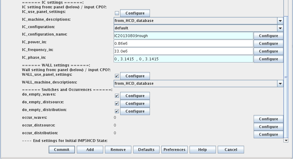
The IC settings panel
The IC settings panel is the list of variables following the line
===== IC SETTINGS =====
Here is a description of the variables in this panel.
- IC_use_panel_settings: If TRUE: use the IC settings panel to configure the IC system. If FALSE: ignore the IC settings panel and use the input CPO.
- IC_machine_descriptions: Select from where the IC hardware description should be taken
- from_input_CPO: use the IC hardware in the CPO provided by the UAL;
- from_HCD_database: use the a HCD-database entry for the tokamak being simulated;
- from_codeparameters: specify the IC settings in the codeparamters of the actor addICant.
- IC_configuration: When using IC data from IC_machine_descriptions=from_HCD_database, then this parameter allow you to select different configurations: either you use the default or a selected configuration. In the latter case the name of the configuration is specified in IC_configuration_name.
- IC_configuration_name: When IC_machine_descriptions=from_HCD_database and IC_configuration=selected, then this parameter allow you to specify the name of your IC configuration. The name is provided as a string and has to be one of the configurations in the list of IC configurations (for details see IMP5 IC-Antennas Database). Note that the configuration is tied to the machine you are simulating, e.g. only ITER configurations can be used when simulating the ITER tokamak.
- IC_power_in: power (W)
- IC_frequency_in: frequency (Hz)
- IC_phase_in: phase of the current in each antenna strap (rad). Vector over all straps. E.g. a dipole phasing for a four strap antenna (JET-A2/ITER) may written as {0,PI,0,PI}, while a current drive phasing would be written as {0,PI/2,PI,3*PI/2} or {0,-PI/2,-PI,-3*PI/2}.
Common IC settings
| Machine | IC_power_in | IC_frequency_in | IC_phase_in |
|---|---|---|---|
| ITER | 20 MW | 54 MHz (central He3 minority at 5.3T) | { 0 , PI , 0 , PI } |
| JET | 7 MW |
33 MHz (central H minority at 2.16T)
37 MHz (central H minority at 2.42T) 42 MHz (central H minority at 2.75T) 47 MHz (central H minority at 3.08T) 51 MHz (central H minority at 3.34T) 33 MHz (central He3 minority at 3.24T) 37 MHz (central He3 minority at 3.63T) 51 MHz (central 2nd harmonic H at 1.67T) 47 MHz (central 2nd harmonic H at 1.54T) 42 MHz (central 2nd harmonic H at 1.38T) 37 MHz (central 2nd harmonic H at 1.21T) 33 MHz (central 2nd harmonic H at 1.08T) |
{ 0 , PI , 0 , PI } (dipole)
{ 0 , PI/2 , PI , 3*PI/2 } (co-current) { 0 , -PI/2 , -PI , -3*PI/2 } (counter-current) |
| AUG | 7 MW |
30.0 MHz (central H minority at 2.0 T)
36.5 MHz (central H minority at 2.5 T) |
{ 0 , PI } |
| Tore Supra | 9 MW |
57 MHz (central H minority at 3.7 T)
63 MHz (central 2nd harmonic H at 2.1 T) 42 MHz (central 3He minority at 3.7 T) 48 MHz (FWEH at 2.1 T) |
{ 0 , PI } |
| WEST (unofficial 2013-08-08) | - MW | 55/57 MHz (central H minority at 3.7 T) |
IC configurations available in the HCD-database
Names of available IC configuration in the machine description database:
| Machine | Configuration name | Description |
|---|---|---|
| ITER | IC20130809rough | A rough unofficial antenna generated to mimic graphical illustrations. |
| JET | IC20130809rough | A rough unofficial antenna generated to mimic graphical illustrations. |
| AUG | IC20130809rough | A rough unofficial antenna generated from a limited number of parameter provided by Roberto Bilato. |
| WEST | FluxAligned | A rough unofficial antenna. The antenna shape is simply aligned to the flux surface, which is the same antenna that Remi Dumont has been using in his initial studies of ICRF in WEST (2013-10-16). |
For detailed descriptions of these antennas see the IMP5 IC-Antennas Database
The Wall settings panel
The Wall settings panel is the list of variables following the line
===== WALL SETTINGS =====
Here is a description of the variables in this panel.
- WALL_use_panel_settings: If TRUE: use the Wall settings panel to configure the wall properties. If FALSE: ignore the Wall settings panel and use the input CPO.
- WALL_machine_descriptions: Select from where the Wall description should be taken:
- from_input_CPO: use the WALL CPO provided by the UAL
- from_HCD_database: use the a HCD-database entry for the tokamak being simulated (see list of available database entries).
- from_codeparameters: Under development.
- from_input_CPO: use the WALL CPO provided by the UAL
WALL configurations available in the HCD-database
| Machine | Configuration name | Description |
|---|---|---|
| ITER | default | from the EDRG machine description database (2013) |
| JET | default | from the EDRG machine description database (2013) |
| AUG | default | from the EDRG machine description database (2013) |
| FTU | default | from the EDRG machine description database (2013) |
last update: 2015-07-23 by tjohnson