Machine Descriptions and Data Mappings
At the forefront of the EDRG activities, the consolidation of the machine descriptions and data mappings for the experimental data on the participating devices is of utmost importance.
Machine Descriptions
Background
The machine description (MD) of a device basically builds on the set of engineering and diagnostic settings characterising any device. This includes, for instance, the vessel/limiter description (for the moment in R-Z domain only), the PF coils and circuiting and lines of sight of diagnostics (an example for ITER is seen below evidencing the vessel+limiter+pfsystems and magdiad CPOs).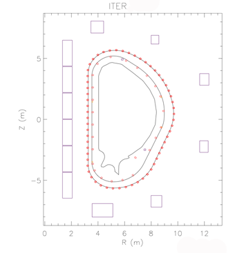
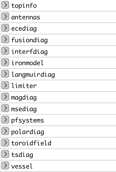
At data structure version 4.09a, the list of CPOs with machine description tags is indicated in the Figure below
MD content on dataversions
| 4.07b | 4.08a | 4.08b | 4.09a |
|---|---|---|---|
| antennas, interfdiag, ironmodel, limiter, magdiag, msediag, pfsystems, polardiag, toroidfield, vessel | antennas, ecediag, interfdiag, ironmodel, limiter, magdiag, msediag, pfsystems, polardiag, reference, toroidfield, tsdiag, vessel | antennas, ecediag, interfdiag, ironmodel, limiter, magdiag, msediag, nbi, pfsystems, polardiag, toroidfield, tsdiag, vessel | antennas, ecediag, fusiondiag, interfdiag, ironmodel, langmuirdiag, limiter, magdiag, msediag, nbi, pfsystems, polardiag, toroidfield, tsdiag, vessel |
Tutorial and specific information on some CPOs
- A good introduction to the machine description concept is found in this User Guide.
- Up to data version 4.07c, the geometry of lines of sight used in some diagnostics (interfdiag and polardiag) was characterized by two angles (poloidal and toroidal). A caveat was found, leading to the adoption of a new set of angles as described in this report. The pivot points became 3 (previously 2) to encompass slightly different entry/exit positions for the reflected beams.
- From data version 4.09a, the limiter, nbi and antennas CPOs use arrays of structures data types. This enabled a more refined description of plasma facing components and the divertor region and both open and closed 'tile' elements. Each NBI and antenna unit is also a dedicated structure.
- Detailed definitions are available for Flux loop position, PFconnections, Langmuir probes and Fusion CPO.
Data Mappings
Background
In regard to the experimental data from a particular shot/device set, the ITM had to develop its own tool to retrieve the data from the experimental databases and populate the corresponding ITM db entry since the latter rarely adopt the same datastructure ontology and different methods/implementation for the databases might exist on different devices. A XML file contains all the mapping essentials, e.g. download method, local signal names, gains and offsets, time base and eventual interpolation option to ensure that only one time base is set for each CPO that is built from multiple local signals. A java code (exp2ITM developed under ISIP), with the MD and DM files as inputs, is then run to connect to the local device database, retrieve the required experimental data and populate the ITM db instance for that shot/device and dataversion. At data structure version 4.09a, the list of CPOs with data mappings tags is indicated in the Figure below (experimental signals are colored in orange; mappings to other CPOs, e.g. equilibrium or coreprof have been set in order to assist the retrieval of simulated data from other databases, e.g. JSP, JSPC)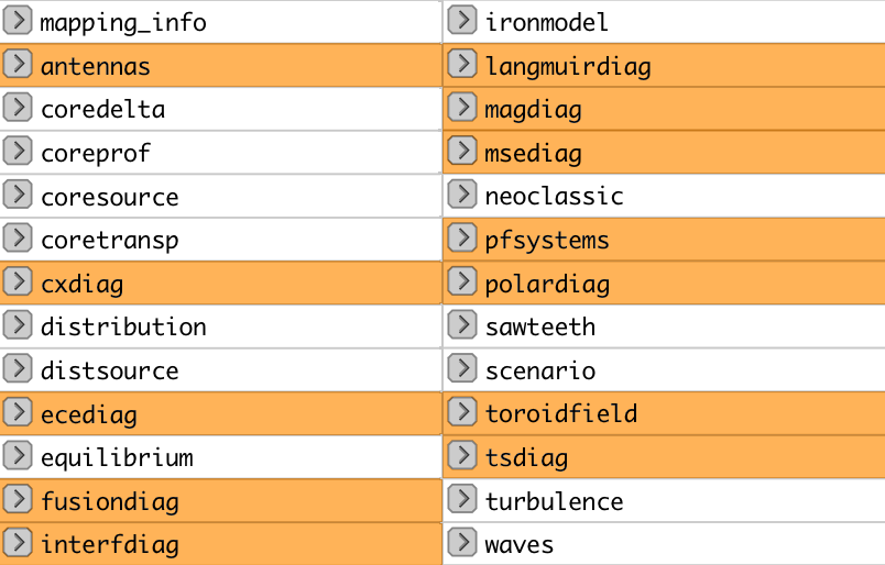
DM content on dataversions
| 4.07b | 4.08a | 4.08b | 4.09a |
|---|---|---|---|
| antennas, interfdiag, ironmodel, magdiag, msediag, pfsystems, polardiag, toroidfield | antennas, cxdiag, ecediag, interfdiag, ironmodel, magdiag, msediag, nbi, pfsystems, polardiag, toroidfield, tsdiag, coredelta, coreprof, coretransp, distribution, distsource, equilibrium, neoclassical, sawteeth, scenario, waves | antennas, cxdiag, ecediag, interfdiag, ironmodel, magdiag, msediag, nbi, pfsystems, polardiag, toroidfield, tsdiag, coredelta, coreprof, coretransp, distribution, distsource, equilibrium, neoclassical, sawteeth, scenario, turbulence, waves | antennas, cxdiag, ecediag, fusiondiag, interfdiag, ironmodel, langmuirdiag, magdiag, msediag, nbi, pfsystems, polardiag, toroidfield, tsdiag, coredelta, coreprof, coretransp, distribution, distsource, equilibrium, neoclassical, sawteeth, scenario, turbulence, waves |
Tutorial on data mappings
- A good starting point to understand the basics of the data mapping concept and how to fill it with the device dependent referecing of the experimental data is found in this User Guide.
- A description on the data mapping concept and processing by exp2ITM (with usage tips) is found in this presentation.
For more updated information on the MD and DM activity please check the md_and_dm project in Gforge
last update: 2019-01-31 by g2dpc